 EN
 DE

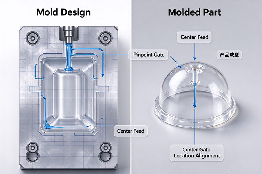
Transparent injection parts are widely used in automotive components, electronic devices, optical covers, and industrial products. While materials such as PC and PMMA offer excellent transparency, achieving a consistent, high-quality appearance requires careful mold design and process control.
One important factor is gate location.
The gate determines where molten plastic enters the mold cavity and influences how the material flows, fills the cavity, and forms the final part. For transparent injection parts, an unsuitable gate design may contribute to visible flow marks, weld lines, gate marks, and uneven surface appearance.
Understanding how gate location affects the molding process can help manufacturers develop better mold designs and reduce appearance-related issues during mold trials and production.
1. Why Does Gate Location Matter for Transparent Injection Parts?
During injection molding, molten plastic flows through the runner system and enters the cavity through the gate. The location and size of the gate influence the flow path, filling pattern, pressure distribution, and the position where separate flow fronts may meet.
For opaque components, some flow-related defects may be less noticeable. However, transparent parts can reveal visual variations that would otherwise go unnoticed.
Gate location should therefore be evaluated according to several factors:
- Part geometry: The shape, wall thickness, and overall dimensions influence how the cavity fills.
- Appearance requirements: Cosmetic surfaces and critical viewing areas require particular attention.
- Material properties: Different resins have different flow and processing characteristics.
- Production requirements: Cycle time, cavity layout, and the intended production volume may affect the choice of gating system.
The goal is not simply to select a convenient gate position. It is to develop a filling strategy that balances appearance, dimensional accuracy, moldability, and production efficiency.
2. How Gate Location Affects Common Appearance Defects
Gate location does not determine every molding defect on its own, but it can influence the conditions under which defects occur.
Flow Marks
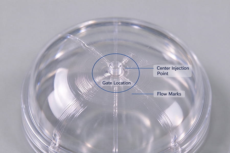
Flow marks may appear as visible lines or variations in gloss on the surface of a molded part. They can be associated with changes in melt flow, cooling behavior, and the interaction between the advancing melt and previously filled regions.
Gate location and gate dimensions influence the flow path and filling behavior. Depending on the part geometry, adjusting the gate position may help improve the filling pattern.
However, flow marks may also result from unsuitable melt or mold temperatures, injection speed, or other processing conditions. The underlying cause should be identified before making design changes.
Weld Lines
Weld lines form when two or more melt fronts meet during cavity filling. Their visibility depends on factors such as melt temperature, flow-front conditions, material properties, and the local geometry.
For transparent components, weld lines can be particularly noticeable because they may affect the appearance and optical characteristics of the part.
Gate placement can influence where the flow fronts meet. Mold designers should evaluate the expected weld-line locations and consider whether they fall within critical viewing areas.
Where necessary, the gate design, filling strategy, venting, or processing conditions may be adjusted to improve the result. In some applications, weld lines cannot be completely eliminated, so their location and acceptability should be agreed upon during development.
Gate Marks
The gate is the connection between the runner system and the molded component. After the part is separated from the runner, a gate vestige may remain.
Its size, shape, and visibility depend on the gate type, dimensions, material, part geometry, and gate removal method.
If the gate is positioned on a highly visible surface, the remaining mark may affect the product’s cosmetic quality. Placing the gate in a less visible or non-critical area may be preferable when the design permits.
For components with demanding appearance requirements, the gate location and acceptable gate vestige should be discussed before the mold design is finalized.
Uneven Filling and Surface Appearance
An unsuitable filling strategy can contribute to variations in flow behavior, localized pressure differences, and inconsistent part quality.
Gate location should be evaluated together with wall thickness, flow length, runner balance, and venting. For multi-cavity molds, the filling balance between cavities also requires attention.
A well-considered gating strategy helps establish a more predictable filling process, although final results still depend on the complete mold design and molding conditions.
3. Common Gate Types for Transparent Injection Molding
Different gate types offer different advantages and limitations. The most suitable option depends on the part design, cosmetic requirements, material, and production targets.
Direct or Sprue Gating
A direct gate feeds molten plastic into the cavity through the sprue, typically in applications where the runner system and part configuration permit this arrangement.
It can be suitable for certain larger components, but the resulting gate mark may be relatively prominent. The gate vestige and its location must be considered when evaluating the cosmetic requirements of a transparent part.
Edge Gating
An edge gate introduces molten plastic through the edge of the part. It is commonly used in conventional cold-runner molds and can be practical for many part geometries.
Its suitability depends on the flow length, wall thickness, gate dimensions, and the visibility of the gate area. The resulting flow pattern and potential weld-line locations should be reviewed during mold design.
Pin-Point or Small-Gate Systems
Small gates can be useful when gate vestige size and automatic separation are important considerations. However, a smaller gate is not automatically better for every transparent part.
Gate dimensions influence filling resistance, shear conditions, and the ability to pack the cavity effectively. The design must be compatible with the resin and the component’s geometry.
Hot Runner and Valve Gate Systems
Hot runner systems deliver molten plastic to the cavity without requiring a conventional solidified runner for each cycle. Valve gate systems use a mechanically controlled pin to open and close the gate.
Depending on the application, these systems can provide greater control over gate placement and filling sequence, and may help reduce visible gate marks or improve filling behavior.
For certain transparent components, a valve gate positioned in a suitable area may offer advantages. However, hot runner and valve gate systems involve additional design, maintenance, and cost considerations. They should be selected according to the project’s technical and commercial requirements rather than used as a default solution.
4. How to Choose the Right Gate Location
Choosing the right gate location requires evaluating the entire part rather than considering the gate in isolation.
Step 1: Review the Part Geometry
Examine the component’s wall thickness, flow length, ribs, bosses, curved surfaces, and other geometric features. These characteristics influence how molten plastic fills the cavity.
For parts with curved or dome-shaped surfaces, the gate position can have a significant influence on the flow pattern and the location of visible flow marks.
Step 2: Identify Critical Cosmetic Areas
Not every surface has the same appearance requirements. Identify the areas that will be visible to end users, the surfaces through which light must pass, and any regions where gate marks or weld lines are unacceptable.
This helps establish where the gate should preferably be located and which potential defects require particular attention.
Step 3: Evaluate the Filling Pattern
Consider how the melt will travel from the gate through the cavity. For complex geometries or demanding cosmetic requirements, mold filling simulation can help compare alternative gate positions and identify potential filling or weld-line concerns.
Simulation results should be interpreted alongside engineering experience and validated through mold trials.
Step 4: Consider Venting and Cooling
Gate location must work together with the mold’s venting and cooling design.
Air needs suitable escape paths as the cavity fills. Poor venting can contribute to trapped gas, burn marks, and other defects. Meanwhile, uneven cooling can affect shrinkage, warpage, and dimensional stability.
These factors should be considered during mold design rather than addressed only after defects appear during trial molding.
Step 5: Validate the Design Through Mold Trials
Even a carefully designed mold requires practical validation.
During mold trials, the molded samples should be evaluated against the agreed requirements for visual appearance, gate vestige, critical dimensions, and other relevant characteristics.
Adjustments to injection speed, mold temperature, packing conditions, or other process parameters may be necessary. If the results remain unsatisfactory, the gate design or other mold features may need to be reviewed.

5. Why Gate Design Is Especially Important for Transparent PC Parts
PC is widely used for transparent covers, protective components, housings, and industrial applications requiring impact resistance.
However, transparent PC parts can be sensitive to processing conditions and may show visible flow-related defects, moisture-related silver streaks, or stress-related optical variations.
Gate design should be considered together with material drying, melt temperature, mold temperature, filling speed, and packing conditions.
For example, a gate position that creates an unfavorable flow pattern may increase the difficulty of achieving the desired appearance. At the same time, changing the gate location alone will not solve defects caused by inadequate material drying or unsuitable processing conditions.
A reliable approach considers the material, part design, mold structure, and injection molding process as one integrated system.
6. Balancing Appearance, Dimensional Accuracy, and Production Efficiency
For industrial customers, an acceptable transparent component must meet more than visual requirements. It may also need to satisfy tight dimensional tolerances, roundness requirements, assembly specifications, and production targets.
A gating solution that improves appearance but creates filling difficulties or excessive cycle time may not be the best overall choice.
During mold development, engineers should balance:
- Surface appearance and gate vestige requirements
- Filling behavior and potential weld-line locations
- Dimensional stability and material shrinkage
- Mold complexity and maintenance requirements
- Cycle time and production efficiency
Early evaluation helps identify potential conflicts before the mold is manufactured and reduces the risk of costly design changes later in the project.
Conclusion
Gate location is an important consideration in the design of molds for transparent injection parts. It influences the filling pattern, potential weld-line locations, gate marks, and the overall appearance of the finished component.
However, achieving high-quality transparent parts requires more than selecting the right gate position. Material selection, mold surface quality, venting, cooling, and injection molding parameters must also be considered.
By evaluating these factors together and validating the design through mold trials, manufacturers can develop a more reliable process for producing transparent plastic components that meet the required cosmetic and dimensional specifications.
Looking for a Transparent Plastic Injection Mold Manufacturer?
Kehui Mold provides custom injection mold manufacturing and precision component manufacturing for industrial applications.
Our team can review your part drawings, material specifications, cosmetic requirements, and production targets to evaluate suitable mold design and gating solutions for your project.
Whether you are developing a transparent PC cover, a clear plastic housing, or another precision injection molded component, early engineering evaluation can help identify potential challenges and establish an appropriate manufacturing approach.
Have a transparent plastic part project? Contact Kehui Mold to discuss your requirements and explore a suitable mold manufacturing solution.

Phone
+86-0769-86066062

info@kehuimold.com


