 EN
 DE

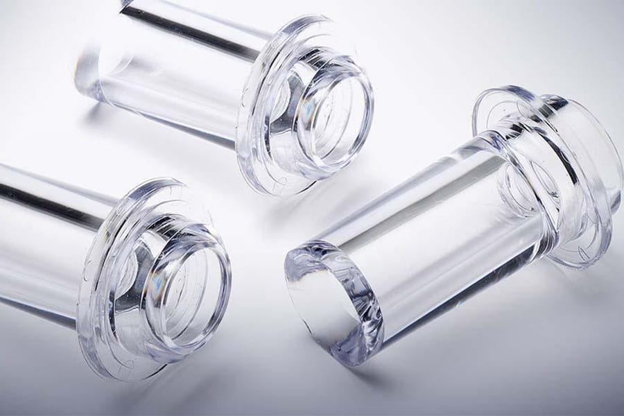
Polycarbonate (PC) is widely used in transparent injection molded parts because of its excellent impact resistance, optical properties, and dimensional stability. Common applications include automotive lighting, protective covers, electronic housings, and industrial components.
However, producing high-quality transparent PC parts can be challenging. Even minor molding defects can become highly visible and affect the appearance and performance of the finished product.
Silver streaks, bubbles, flow marks, weld lines, and haze are among the most common issues in transparent PC parts injection molding.
Understanding their causes and prevention methods helps manufacturers improve product quality and achieve more consistent molding results.
1. Silver Streaks of Transparent PC Parts
What do they look like?
Silver streaks appear as thin, silvery or whitish lines on the surface of transparent plastic parts, usually following the direction of material flow.
Common causes:
- Moisture in PC resin due to insufficient drying.
- Material degradation caused by excessive temperature or prolonged residence time.
- Air or volatile gases during the molding process.
How to prevent them:
- Dry PC resin according to the material manufacturer’s recommendations.
- Prevent dried resin from absorbing moisture during storage and handling.
- Control melt temperature and material residence time.
- Optimize injection speed and mold venting.
Since PC is a hygroscopic material, proper material drying is one of the most important steps in preventing silver streaks.
2. Bubbles and Air Traps
What do they look like?
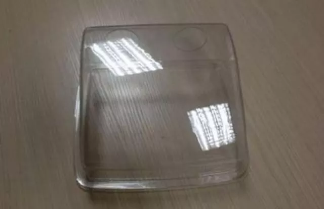
Bubbles appear as visible voids or air pockets inside transparent plastic parts, affecting their optical appearance and sometimes structural performance.
Common causes:
- Moisture or volatile substances in the material.
- Poor mold venting.
- Air trapped during cavity filling.
- Localized shrinkage caused by uneven wall thickness or insufficient packing.
How to prevent them:
- Ensure proper material drying and handling.
- Improve mold venting to allow trapped air to escape.
- Review gate location and filling patterns.
- Optimize packing pressure and holding time.
- Maintain appropriate wall thickness and cooling conditions.
It is important to distinguish gas-related bubbles from vacuum voids caused by material shrinkage, as they require different corrective actions.
3. Flow Marks and Weld Lines
What do they look like?
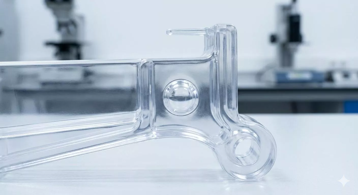
Flow marks appear as visible lines or variations in gloss on the surface. Weld lines form where two or more melt fronts meet during cavity filling.
Both defects can be particularly noticeable in transparent components.
Common causes:
- Unsuitable gate location or gate dimensions.
- Inappropriate injection speed.
- Low or inconsistent mold temperature.
- Poor venting.
- Complex part geometry or uneven wall thickness.
How to prevent them:
- Optimize gate location and dimensions.
- Adjust injection speed and melt temperature.
- Maintain suitable mold temperature.
- Improve venting near potential weld-line locations.
- Use mold flow simulation when appropriate to evaluate filling behavior.
For transparent parts, gate design should be considered early in mold development, especially when critical viewing areas must remain visually clean.
4. Black Spots and Material Contamination
What do they look like?
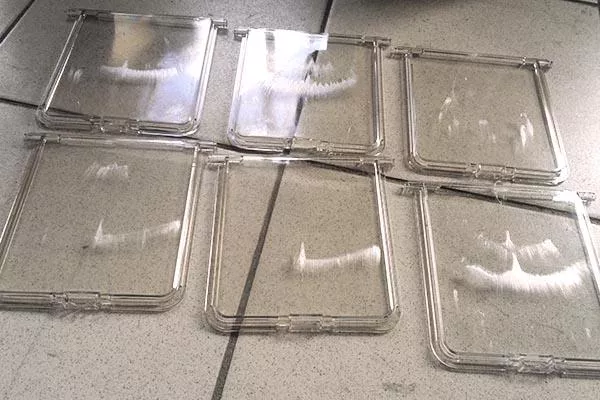
Black spots appear as small dark particles or discolorations on or inside transparent plastic parts. Even tiny particles can be noticeable because of the material’s transparency.
Common causes:
- Dust or foreign material contamination.
- Material degradation inside the injection unit.
- Excessive melt temperature or prolonged residence time.
- Residual material from previous production runs.
How to prevent them:
- Keep raw materials and processing equipment clean.
- Clean the injection unit and hot runner system when necessary.
- Avoid excessive processing temperatures.
- Follow appropriate material purging procedures.
- Inspect raw materials and molded samples regularly.
Clean material handling and stable processing conditions are essential for producing high-quality transparent PC components.
5. Haze and Loss of Transparency
What does it look like?
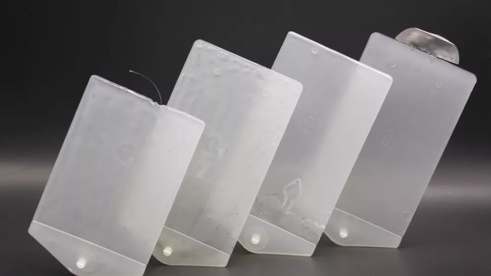
Haze refers to a cloudy or milky appearance that reduces the clarity of transparent plastic parts. Instead of a clear finish, the component may appear dull or foggy.
Common causes:
- Moisture-related material degradation.
- Material contamination or incompatible additives.
- Poor mold cavity surface finish.
- Internal stress and optical variations.
- Unsuitable processing conditions.
How to prevent it:
- Select suitable PC resin with consistent material quality.
- Follow the resin manufacturer’s drying and processing recommendations.
- Maintain clean production conditions.
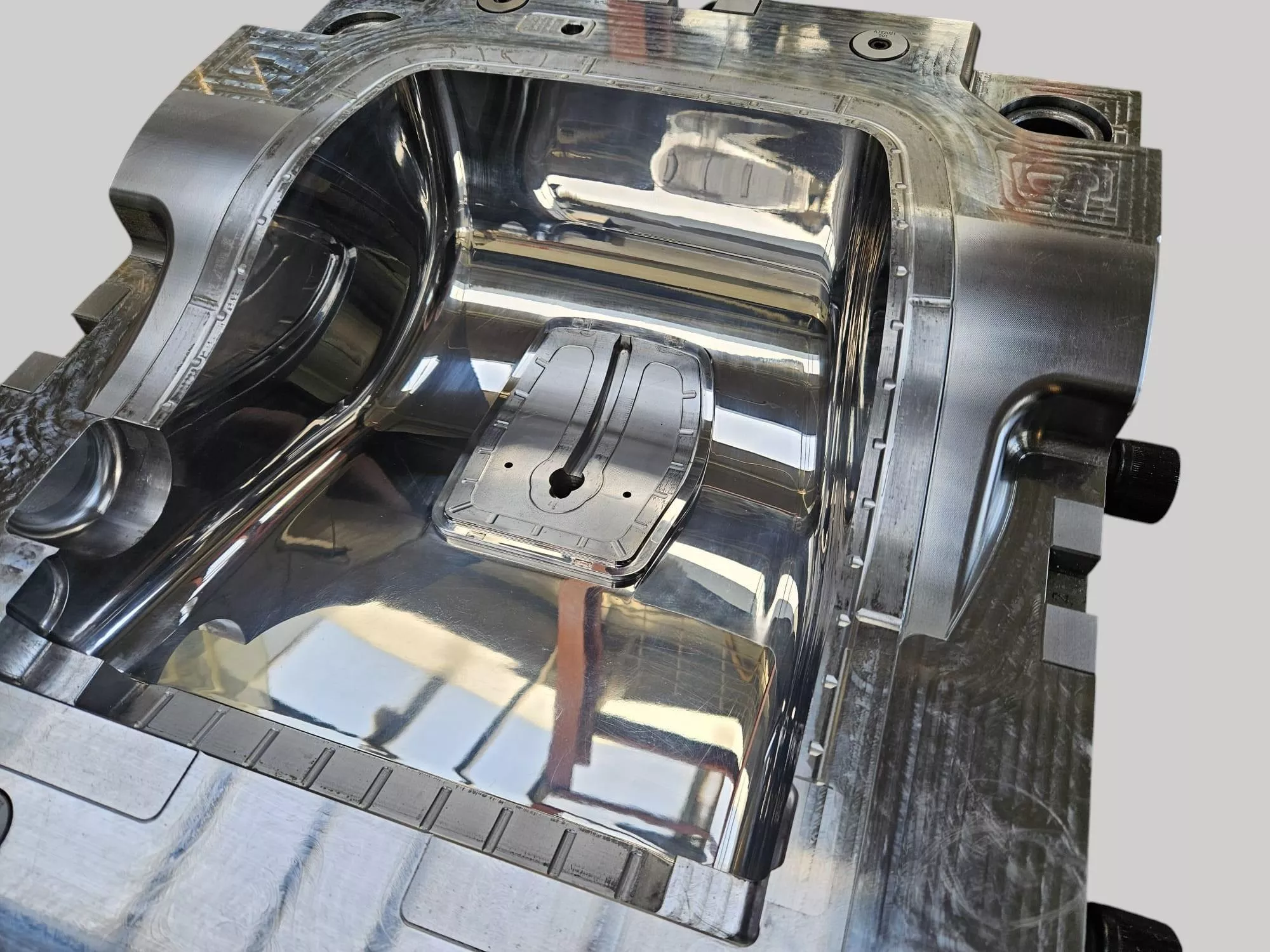
- Ensure proper mold cavity and core polishing.
- Optimize molding and cooling conditions.
- Evaluate internal stress when optical requirements are demanding.
For applications requiring high optical clarity, both mold surface quality and the optical properties of the molded material need to be considered.
6. Internal Stress and Stress Cracking
What do they look like?
Internal stress may not always be visible immediately after molding. However, excessive residual stress can affect optical appearance and increase the risk of cracking under certain mechanical or chemical conditions.
Common causes:
- Excessive injection or packing pressure.
- High shear stress during filling.
- Uneven cooling.
- Unsuitable gate design.
- Sudden changes in wall thickness.
How to prevent them:
- Optimize injection speed and pressure profiles.
- Review gate location and filling balance.
- Improve cooling system design.
- Avoid unnecessary wall thickness variations.
- Evaluate residual stress when required by the application.
For demanding transparent PC applications, stress evaluation under polarized light may help identify optical variations associated with residual stress.
7. How Mold Design Affects Transparent PC Parts Quality
Injection molding parameters are important, but mold design also plays a major role in preventing defects.
Several factors should be evaluated during mold development:
- Gate Design: The gate position and type influence filling behavior, weld-line locations, and gate marks.
- Mold Polishing: The cavity and core surface finish directly affect the appearance of molded parts. High-quality polishing is often necessary for transparent components.
- Mold Venting: Proper venting helps release trapped air and gases during cavity filling.
- Cooling System: Balanced cooling helps reduce uneven shrinkage, warpage, and residual stress.
These factors should be considered together rather than treated as separate solutions after defects appear during mold trials.
Conclusion
Transparent PC parts injection molding requires careful control of material preparation, mold design, and processing conditions.
Common defects such as silver streaks, bubbles, flow marks, weld lines, black spots, haze, and internal stress can affect the appearance and performance of finished components.
Proper resin drying, suitable gate design, effective mold venting, high-quality cavity polishing, and balanced cooling all contribute to more reliable molding results.
Identifying potential problems early in mold development can help reduce unnecessary adjustments and improve production consistency.
Looking for a Transparent PC Injection Mold Manufacturer?
Kehui Mold provides custom injection mold manufacturing and precision plastic component manufacturing for industrial applications.
From mold design and precision machining to cavity polishing and injection mold trials, our team considers the key manufacturing factors that influence transparent plastic part quality.
Whether you are developing a transparent PC cover, protective housing, or another precision molded component, we can review your drawings and technical requirements to evaluate a suitable manufacturing solution.
Have a transparent PC parts molding project? Contact Kehui Mold to discuss your requirements and explore how we can support your next project.

Phone
+86-0769-86066062

info@kehuimold.com


